|
EPAC
- 300 - Features and Specifications
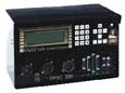 Display
- Display
-
- LCD
alphanumeric backlit display
- 8
Lines - 40 characters / line
Traffic
Control -
- 16
Vehicle Phases
- 16
Pedestrian Phases
- 4
Timing Rings -
-
Phase ring assignments of
- Ring
- Phase
Next
- Concurrent
- 16
Overlaps
- Overlap
phase assignments of
- Trailing
Green
- Yellow
- Red
- Control
up to 80 Detectors
-
Detector Assignments as phase vehicle or pedestrian
detector with:
-
Delay, Extend, or Switch
-
System, Speed, or Count detector
- Can
use Type 2
-
Controller Unit Phase Omit
-
Phase Hold via alternate ABC connector I/O modes
-
Can assign the Type 2 Controller Unit Signal Drive Outputs
to any pin set
-
Phase On
-
Phase Next
-
Phase Check
- Adaptive
Maximum Routines
- Dynamic
Maximum Parameters
- Dynamic
Maximum Values
- Adaptive
Protected/Permissive Routines
- Ring
Timer Status Display denotes:
-
Up to six active timers and/or states per ring for two
rings simultaneously
-
Coord Control Source/Pattern/Cycle Counter
-
Phase On/Next Phase Vehicle Call/Recall
-
Phase Pedestrian Call/Recall
-
Phase Hold/Omit/Ped Omit
Coordination
-
- Sixteen
Timing Plans - One for each Dial/Split combination w/ three
offsets each.
-
Each timing plans provides:
-
Cycle timing
-
Phase split timing
-
Phase modes
- Six
Operational Modes can be selected for continual operation
or can operate with a specific pattern
- Permissive
Mode provides non-actuated coord phase vehicle and
pedestrian modes with permissive windows opened phase-by-phase
to the non-coord phases.
-
Yield Mode provides non-actuated coord phase vehicle
and pedestrian modes with a single permissive window
for all non-coord phases.
-
Permissive Yield Mode provides for actuated coord
phase vehicle and pedestrian modes with permissive windows
opened phase-by-phase to the non-coord phases. Additionally,
the coord phase vehicle can extend its green time at
the beginning of the first permissive window.
-
Permissive Omit Mode provides operation similar
to Permissive Yield except that the coord phase, once
terminated, is prevented from occurring prior to the
end of the last permissive.
-
Sequential Omit Mode provides operation similar
to Permissive Yield except the permissive is a phase-by-phase
sliding window (only one phase in a ring will be allowed
service at any time).
-
Full Actuated Modes provides operation similar to
Permissive Yield except that any phase can be serviced
and re-serviced in the standard sequence following the
first permissive and through the last permissive.
-
Four Correction Modes to determine the method in which
the coordination will bring the background cycle in sync
with the system cycle.
-
Three Maximum Modes to determine whether Maximum 1,
Maximum 2, or Maximum Inhibit will be effective when coordination
is in control.
-
Two Force Modes to determine whether the non-coord phase
force will be based on a position in the background cycle
or on the Timing Plan Phase Split Time.
-
Two Offset Modes to determine whether the Offset is
calculated based on the Start or End of the first coord
phase Green.
-
Local Traffic Responsive Override to enable selection
of patterns based on computed volume plus occupancy of selected
detectors.
-
Virtual Split Routine on all operational modes, which
provides for actuated coord phase vehicle and pedestrian
modes. This control provides for a period of time of each
cycle, which is distributed to the Coord Phase(s) or non-coord
phases, based on Coord Phase vehicle traffic activity.
-
Coordination activity can be monitored on a Coord Active
Status display which denotes:
-
Operation, Correction, Maximum, and Force Mode
-
Cycle Time Parameter, Countdown, and Adjustment
-
Offset Time Parameter, Current, and Adjustment
-
Phase Time Parameter, Countdown, Adjustment, Mode
Time
Base Control -
Internal Time Base Control is a highly flexible routine operating
within the EPAC300 Series Controller Unit.
- Automatic
adjustments for leap year and daylight savings changes.
- 250
Events for the control of Pattern Selection, Free, Flash,
Dimming, Detector Diagnostic Parameters, System Detector
Logging, 3 Auxiliary Functions, 8 Special Functions, 16
Traffic Functions.
- 99
Day Programs for programming events to occur within the
weekly programs and for exception days.
- 10
Week Programs for programming events to occur within different
weekly schedules.
- Time
Base Control provides programming of exception days and
weekly programs to begin over a year in advance in the familiar
Month/Day/Year form.
- Time
Base activity can be monitored on a Time Base Status display
which denotes:
- Day,
Date, and Time
-
Active Day and Week Program
-
Active Pattern
-
Active Auxiliary, Special, and Traffic Function
Preemption
-
Internal Preemption is a highly flexible routine operating
within the EPAC300 Series Controller Unit.
- Included
are SIX Preempt routines providing complete signal control.
Each routine provides the capability to program the state
of the outputs for two Green Intervals. Outputs which are
not normally on can be activated during preempt. The capability
exists for limited cycling during the preempt dwell. The
capability exists to link multiple routines to form more
complex routines. Delay, Extend Duration, Max Call, and
Lock Out timings exist for each routine.
- Included
are SIX Priority Routines providing complete phase control.
Each routine provides the capability to program the phase(s)
which are to be active in the dwell state. Delay, Extend
Duration, Max Call, and Lock Out timings exist for each
routine.
- Preempt
activity can be monitored on a Preempt Status display which
denotes:
- Preempt-In
Control, Interval Timing, and Interval Countdown
-
Individual Preempt Status and Timing
-
Individual Priority Status and Timing
Reports
-
The EPAC300 Series Controller Unit provides an extensive report
capability. Each report entry includes the Date and Time of
occurrence.
-
Local Alarm Log with the capacity to store 120 events.
Over 100 different events can be stored in this log.
- Comm
Fault Log with the capacity to store 60 events. Fourteen
different communications type faults can be stored in this
log.
- Detector
Fault Log with the capacity to store 60 events. Ten
different detector diagnostic type events can be stored
in this log.
-
System Detector Log with the capacity to store 96 events.
Each event will note the raw volume, raw occupancy, average
volume, and average occupancy on up to 8 detectors.
- MOE
Log with the capacity to store 24 events. Each event
will note the Volume, Stops, Delay, and Green utilization
on each phase for the active pattern.
- Speed
Log with the capacity to store 24 events. Each event
will note the percentage for vehicles below, within, and
above a user-defined speed for the active pattern.
- Volume
Count Log with the capacity to store 72 events. Each
event will note the volume counts recorded by up to 24 detectors.
Diagnostics
- A Resident
Diagnostic Program is standard in the EPAC300 Series Controller
Unit. In addition to the extensive displays to aid in intersection
setup, monitoring, and operation, the resident diagnostic
program enhances maintenance and troubleshooting. Many of
the diagnostic routines execute automatically and continually,
verifying unit integrity. Diagnostic analysis is displayed
or logged in English.
- Automatic
Diagnostics begin at power up and continue as long as
the unit is operating.
- Power
Up Diagnostics include PROM, RAM, EEPROM, Real-Time
Clock, and Processor checks. Failures will result in the
unit not enabling the Fault Monitor or Voltage Monitor outputs
while the display shows messages such as "PROM TEST: FAILED".
- Monitor
Compatibility Programming Diagnostics include a verification
that the Monitor Program Card Programming is consistent
with Controller Unit Sequence.
- Monitor
Field Status Diagnostics include a redundant test for
conflicting channels by being active simultaneously.
-
Cycling Diagnostics
include a verification that phases with serviceable calls
are receiving service in a timely manner.
- Detector
Diagnostics include a verification that detector activity
is within thresholds defined by the user.
- Port
1 Message Display - This status display will indicate
the status of each bit in the requested message.
- Port
2 Comm Status Display -This status display will indicate
the port settings (i.e., 1200, 8N1), line status, carrier
status, when transmitting, and when receiving.
- Port
3 Comm Status Display - This display is a duplicate
of the Port 3 display.
- Hardware
Input Status Display - This display will indicate the
status of every hardware input (i.e., On/Off).
- Hardware
Output Status Display - This display will indicate the
status of every hardware output (i.e., On/Off.)
- Other
features of the resident diagnostics program are available
on user request, and when combined with an input/output
monitor provide total indication of unit operation. For
trend analysis, the failures are logged with date and time
and remain available for display as needed.
TS
2 Advantages
- Controller
Assemblies that conform to NEMA TS 2-1992 Standard provide
increased capability.
- Controller
Assemblies with TS 2 Detector Racks consume less power and
provide additional diagnostic data to the Controller Unit
via the SDLC port. The Controller Unit can take corrective
action much earlier than it could, based on its own internal
diagnostics.
- Controller
Assemblies with TS 2 Monitors provide additional diagnostic
data to the Controller Unit via the SDLC port. The Controller
Unit can take corrective action for improper Program Cards
as well as Monitor failures.
Controller
Types -
The EPAC300 Series Controller Unit supports both NEMA TS 2
Type 1 and TS 2 Type 2 Actuated Controller Units.
- The
TS 2 Type 1 Actuated Controller Unit is a performance-oriented
controller unit using a high speed data channel between
all major components within the Terminal and Facilities
as follows:
- Port
1 Connector -- a High Speed data channel connecting
the controller unit, monitor, detectors, and back panel.
-
Port 2 Connector -- a RS-232 (EIA/TIA Standard DTE Interface)
in 25-pin configuration supporting baud rates from 1200
to 19200 bps. Used to interface with a Personal Computer,
Printer, or a like controller unit.
-
Port 3 Connector -- Used for On-Street Communications
and available in the following forms:
-
1200 Baud FSK Modem (2-wire or 4-wire)
-
Fiber Optic Modem with two ports supporting baud
rates from 1200 to 19200 bps.
-
Two RS-232 (EIA/TIA Standard DTE Interface) in 9-pin
and 25-pin configurations supporting baud rates
from 1200 to 19200 bps.
- The
TS 2 Type 2 Actuated Controller Unit includes all the features
of the Type 1 and adds the following:
-
MSA, MSB, and MSC connectors for data exchange with
the Terminals and Facilities. This provides a degree
of downward compatibility with NEMA TS 1 counterparts.
-
37-pin "D" connector for backward compatibility with
TS 1 counterpart.
Security
-
The EPAC300 Series Controller Unit offers a user specified
security code entry before data can be altered. This security
code entry is never required in order to view any parameter.
The EPAC300 Series Controller Unit can disable security code
requirements for perpetual access.
Hardware
Design -
- The
EPAC300 Series Controller Unit is designed for efficient
operation and ease of maintenance. The metal chassis has
easy access to the boards for testing without disassembly.
There are minimum components inside the EPAC300 for maximum
reliability.
- EEPROM
technology is used to retain all timing and control parameters
to insure the accuracy of traffic control parameters, even
during power outages. No batteries are required for retention
of traffic parameters. Event logging and the Time Base clock
use RAM memory for those functions with battery support.
2070
- Features and Specifications
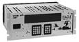 HARDWARE
FEATURES - HARDWARE
FEATURES -
- Two
keypads
- Metal
housing compatible with CALTRANS Type 170 Controller Unit
and Facilities
- Serial
motherboard
- 3U
Five Slot/Connector VME Cage Assembly
- Single
96-pin DIN connectors for all plug-in boards
CPU
FEATURES -
- Standard
VME 3U size
- Motorola
68360 microprocessor, 25 MHz
- 4
spare VME 3U slots for off-the-shelf boards
- 4
MB of RAM (minimum)
- 256K
battery-backed SRAM (minimum)
- Time
of Day Clock
- OS-9
version 3.0 Operating System
MISCELLANEOUS
FEATURES -
- Direct
access of serial ports from application software
- Power
supply module independent, self-contained
- Input
protection
- +5
VDC standby power using capacitor backup
- Circuitry
monitoring for safety features
FIELD
I/O FEATURES -
- Motorola 68302 Microprocessor
- Socket EPROM firmware for operational
software
- Parallel I/O Ports -- 64 bits each input
and output
- SDLC compatible communication with CPU
Module
- External EIA 485 Net
OPTIONAL
FEATURES -
- ASYNC/Modem
Serial Comm Module
-
2 RS232 Communications, configured as Type 170 C2 and
C20 connectors (2070-7)
-
FSK Communications, configured as Type 170 "Audio in"
and "Audio out" connectors (2070-6)
- 2070
controller compatible with NEMA Interface Module to form
CALTRANS standard 2070N controller unit
-
NEMA "A," "B," and "C" connectors
-
80 Bits of input and 96 bits of output
-
63 pin "D" plug connector
SPECIFICATIONS
-
- Temperature:
-37°C to +74°C
- Physical
Dimensions (H x D x W): 177mm x 260mm x 483mmWeight: <11
kg
- Power
Consumption: 75 watts (typical); 150 watts (maximum)
2070-Lite
- Features and Specifications
The
Model 2070Lite ATMS Controller Unit is a low cost version
of the Model 2070 designed for basic intersection control.
HIGHLIGHTS
-
- VME
chassis is removed
- MCU
attaches to the transition module
- Does
not include a keypad or display (a low-cost, 8 line by 40
character display is optional)
- Is
programmed via serial port
- Also
has the option of a serial field I/O connection to BIU or
SIU
The 2070Lite
can be upgraded to a standard 2070 by simply adding a VME
chassis. The power supply is the same in both the standard
2070 and the 2070Lite. For more information and specifications,
please see the Model 2070.
2070-NEMA
- Features and Specifications
 The
initial effort to bridge the gap between CALTRANS and NEMA
traffic control equipment was made by EAGLE when the MAGNUM
card, with NEMA interface features, was introduced for placement
in a CALTRANS Type 170 or Type 170E controller unit. The
initial effort to bridge the gap between CALTRANS and NEMA
traffic control equipment was made by EAGLE when the MAGNUM
card, with NEMA interface features, was introduced for placement
in a CALTRANS Type 170 or Type 170E controller unit.
CALTRANS
has now completed specifications for a controller unit to
further efforts toward compatibility with NEMA. The basis
of the controller unit is the power-enhanced and versatile
Model 2070. For NEMA compatibility, the Model 2070 unit allows
the attachment of a lower section which contains the NEMA
TS1 "A," "B," and "C" connectors, a "D" connector, and an
RS232 communications port.
The addition
of the lower NEMA compatible section to the Model 2070 and
the replacement of the 2070-2 module with a 2070-2A module
creates the CALTRANS specified Model 2070N controller unit,
which is specifically designed to function in a NEMA TS1 cabinet.
The Model
2070N allows NEMA equipment users to capitalize upon the Model
2070's open VME bus architecture features. For instance, the
control of a variable message sign can be added by a module
installation.
MODEL
2070 CPU FEATURES -
- Standard
VME 3U size
- Motorola
68360 microprocessor, 25 MHz
- 4
spare VME 3U slots for off-the-shelf boards
- 4 MB
of RAM (minimum)
- 256K
battery-backed SRAM (minimum)
- Time
of Day Clock
- OS-9
version 3.0 Operating System
SEPAC
- Application Software for 2070
SEPAC
software brings the functionality of the EPAC NEMA application
software to the 2070 family of controllers.
- EPAC
has over 70 man-years of development to make it the most
functional application software available.
- Fully
compatible with all Eagle TCS Signal Control Software Systems.
-
ACTRA - Eagle's newest Intelligent Transportation Management
Software. Integrated, powerful, modular, intuitive,
and expandable. Easy to use GUI with all the functionality
of a Windows 95/98/NT interface.
-
MARC-NX - Enhanced closed-loop software with Windows
95/98/NT interface.
- SCOOT
- The most proven Adaptive Control Software
 Visit
the Eagle TCS Website Visit
the Eagle TCS Website
 Need
more information? Contact Us. Need
more information? Contact Us.

|